ABSTRACT
Presented herein is a description of how the machining axes and diamond tool on a 5-axis diamond turning machine can be used to position a part precisely on a vacuum chuck. The example below describes part positioning of a small (2.5 mm diameter) plastic freeform lens that cannot be tapped into place using traditional processes.
INTRODUCTION
In recent years, 5-axis diamond turning machines have primarily been used to manufacture freeform optics via their diamond turning, milling, flycutting or raster cutting abilities. It is possible, however, to apply five-axis diamond turning machines (DTM) to a much wider range of optical fabrication problems. We have previously demonstrated how they enable in-situ, noncontact 3D metrology and skew turning [1]. Presented herein is another powerful application of a 5-axis diamond turning machine. The concept of automated on-machine part centering has been around for some time [2], though this is usually done by using an independent actuator. Similarly, in-situ optical metrology has been used successfully to achieve precise workpiece centering [3]. However, with a 5-axis diamond turning machine, the diamond tool itself becomes the actuator. When integrated with an in-situ metrology sensor, the process of actuating the diamond tool can position small parts that cannot be manually centered to uncertainties of less than 1 µm.
The present example is of a small plastic freeform lens that requires two optical surfaces to be positioned relative to one another within 1 um. As shown in Figure 1, the example lens is 2.5 mm in diameter and consists of two aspheric cylinders situated on a cylindrical disc with a clocking flat.
 FIGURE 1. A small polymer free-form lens with two aspheric cylinder surfaces (S1 and S2). The surfaces are located on the diamond turning machine via the indicated datums. The lens diameter is 2.5 mm.
Manipulating a small lens with the rake face of a diamond tool seems straightforward, but achieving repeatable motion can be a challenge. The chief determinant of motion repeatability during an actuation operation is the friction at the interface between part and chuck [4]. To achieve the highest degree of repeatability, a kinematic support arrangement was achieved by diamond turning a set of sinusoidal bumps on the part chuck as shown in Figure 2. With a height of 40 µm, the bumps guaranteed a deterministic contact because they do not depend on the flatness of the mating part surface.
Using a specialized vacuum chuck, a lens blank is placed on a 5-axis diamond turning machine equipped with a chromatic confocal sensor. The sensor is located under the diamond tool to allow measurement of the part position as shown in Figure 3.
 FIGURE 2. Measurement of sinusoidal bumps diamond turned on the vacuum chuck interface for mounting the lens shown in Figure 1.
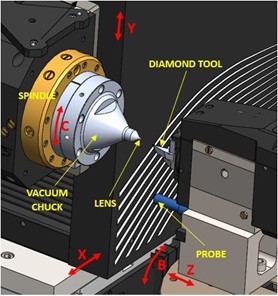 FIGURE 3. Setup of 5-axis diamond turning machine for positioning small plastic lens and verifying its location using measurement probe as shown.
PROCEDURE
The alignment process begins with a rough, oversized cylindrical blank that is manually placed on the previously described kinematic vacuum chuck. Because small, plastic lenses can be challenging to handle (the example part mass is 6 mg), the part is held on its outer edge via a set of vacuum tweezers as shown in Fig. 4. Vacuum tweezers provide more precise control when handling small lenses over standard tweezers due to the constant vacuum force applied over a small area. If the lens to be pushed has a non-axisymmetric surface on either side, like the example lens described here, it is necessary for the blank to have a clocking feature for orientation about its axis. In this case, a clocking flat provides a straightforward geometry that is easily accessed and measured. Before beginning the centering process on the example lens, the clocking flat is aligned so that it is parallel with the vertical Y-axis plus 45 degrees. Doing this ensures that the diamond tool is always pushing exclusively on the OD itself during the alignment process. Specifically, clocking flat alignment is accomplished by offsetting the C-axis by the angle computed after measuring two points on the flat with the probe that are a known vertical distance apart.
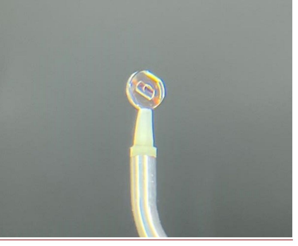 FIGURE 4. Photograph of the example part shown in Figure 1 held with a set of vacuum tweezers for manipulation and rough placement.
Through a series of programmed moves, the tool pushes the part onto center along the Y-axis based on initial knowledge of the lens rough OD, as shown in Figure 5. Each push is programmed to stop once the tool reaches the measured part radius along the Y-axis, assuming the diamond tool is vertically centered on the main spindle. Once the first push operation is performed, the Baxis is rotated 90° to allow the OD datum to be measured by the probe. First, the runout is measured. Second, the tilt of the clocking flat is recomputed, and the C- axis is offset by technique described above; it is necessary to recompute the tilt of the clocking flat after each iteration of four pushes because each vertical push may translate the lens horizontally a small amount that depends on the friction between the lens/fixture and lens/tool interfaces. Based on these measurement results, the second push operation is adjusted to bring the part into center and the C- axis clocking offset is modified to orient the overall clocking of the part. Once the part runout is within acceptable limits, the S1 surface, S1 face datum, and OD datum can be diamond turned. Optionally, the clocking flat can also be raster cut along the Y-axis with the same diamond tool, though this was found to be unnecessary in most cases as conventional machining can achieve flatness of ~2 µm over such small distance. The lens is then flipped on the vacuum chuck and the process repeated, this time the S2 face datum (except the clocking flat) is diamond turned.
 FIGURE 5. A diamond tool is used to push the part to spindle center through four moves using the Y and C-axes of the DTM. The clocking flat is rotated to 45 degrees relative to the machine axes so it does not interfere with the pushing operation.
After diamond turning the second side of the lens, the relative location and thickness of the lens surfaces can be verified with the confocal sensor pointed along the X-axis. In this case, it is necessary to place the clocking flat against the vacuum chuck and use the C-axis to flip the lens 180° between measurements, shown in Figure 6.
 FIGURE 6. To confirm relative placement of the optical surfaces after the described alignment and machining procedure, the clocking flat on the part is placed on the vacuum chuck for measurement. The part is then rotated for measuring S1 as shown in a.) and for measuring S2 after a 180° rotation as shown in b.
RESULTS

FIGURE 7. Measurement data acquired with probe during process illustrated in Fig. 6. With data from multiple surfaces collected, it is possible to determine relational positions of each surface relative to one another.
Measurement data collected during metrology operations on all sides of lens is shown in Fig. 7. The data sets for each surface and the OD surfaces are separated and the relational position between each is determined to gauge the accuracy of the part positioning method.
CONCLUSION
By using the motion axes of a 5-axis diamond turning machine, a method for orienting small lens surfaces precisely for diamond turning was demonstrated. This method has been used to diamond turn small prototype anamorphic lenses with alignment uncertainties of less than 1 µm.
In a more general sense, it can also be noted that a diamond turning machine can be multi-functional with machining, metrology and robotic actuation all in one package. Multiple axes of motion expand the application field and add more flexibility to the range of operations beyond multiaxis machining. Also, it should be noted that the multi-purpose nature of an accurately aligned diamond tool is a powerful component in increasing the precision and efficiency of manufacturing at the ultraprecision level.
REFERENCES
[1] Sohn A, Naples N, Single-Point Diamond Turning of Features with Large Azimuthal Slope, Proceedings, ASPE 2021 Annual Meeting.
[2] Furst SJ, Dow TA, Garrard KA, Sohn A, Automated Part Centering with Impulse Actuation, J. Manuf. Sci. Eng. Feb 2010, 132(1): 011007 (9 pages)
[3] Wenzel C, Winkelmann R, Klar R, Philippen P, Garden R, Pearlman S, Pearlman G, Advanced Centering of Mounted Optics,
[4] Furst SJ, Dow TA, Automated Handling Technology for Precision Two-Sided Parts,
PEC Annual Report 2008, NCSU, pp 167185.
Extended abstract published with permission from the American Society for Precision Engineering.
Click here to read the extended abstract.